
- Local: (516) 346-4636
- Toll-Free: (800) 886-6060
- Email: kflynn@nationalwebbing.com
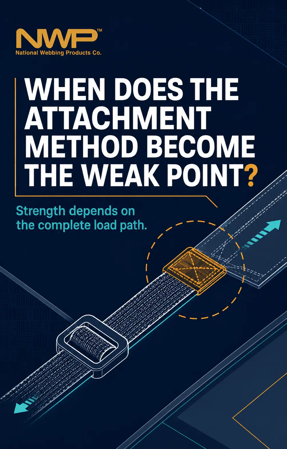
A finished strap does not carry force through the webbing alone. The load also moves through folds, stitch lines, welded areas, hardware, and the points where the assembly connects to the larger product. An attachment becomes the weak point when its construction, geometry, workmanship, or loading condition limits the assembly before the webbing reaches its own tested capacity. At National Webbing, we evaluate attachment choices as part of the strap design because a strong roll of nylon does not automatically produce a strong finished assembly. The useful question, then, is not whether sewing, welding, or hardware is "strong," but whether the selected attachment has been defined and validated for this exact construction and use.
Raw-webbing data describes a defined material specimen under a defined test. For example, ASTM D6775 covers breaking strength and elongation testing for textile webbing, tape, and braided materials using a specified clamping method. Once you fold, pierce, sew, weld, or route webbing through hardware, the load path changes. A finished strap must therefore be evaluated as its own assembly rather than assigned the raw webbing number by default.
Geometry matters because force is rarely distributed perfectly across every yarn, stitch, and contact surface. A narrow bearing edge can bend or concentrate the webbing, an off-axis pull can load one side of a seam, and incorrect routing can allow slip before any material breaks. Hardware can also rotate, crush, or abrade the webbing in ways that a straight material test does not reproduce. These are not reasons to distrust nylon webbing; they are reasons to specify and test the actual interface you will use.
Sewing is versatile because the pattern can distribute load across a controlled area, but the visible outline of a stitch pattern is not enough to establish performance. ASTM D6193 identifies stitch type, seam type, stitch density, thread characteristics, thread tension, fabric characteristics, and end-use requirements as relevant variables in sewn products. Changes to any of those elements can change how the seam loads and how it fails. The attachment specification should therefore control the complete construction rather than naming only "box stitch" or "bar tack."
ASTM D1683/D1683M is useful because it distinguishes several sewn-seam outcomes, including stitching failure, seam slippage, yarn displacement, and fabric failure. The standard also states that its test does not predict actual wear performance, which is an important limitation. A successful pull test can answer a defined strength question, but it does not prove resistance to every cycle, abrasion pattern, contamination condition, or field-use behavior. Those concerns require separate validation when the application makes them relevant.
National Webbing offers assembly methods that include sewing, ultrasonic welding, cutting, punching, hook and loop, and integration with plastic or metal hardware. Each process changes the material differently and therefore needs its own specification and validation plan. Welding depends on compatible materials, geometry, energy, pressure, and process control; punching removes or displaces material and can create a concentrated load path; adjustable hardware depends on routing, surface interaction, and tail retention. Don't select a method only because it looks clean, is fast, or is familiar from another product.
|
Attachment |
What It Can Accomplish |
Variables That Must Be Defined |
What the Sample Must Validate |
|
Sewn fold or loop |
Permanent joint or fixed-hardware capture. |
Layers, fold, seam, stitch, thread, orientation, and workmanship. |
Fit, seam integrity, damage, and specified load direction. |
|
Ultrasonic weld |
Bonded joint without sewing when compatible. |
Materials, overlap, weld area, process settings, and acceptance limits. |
Bond consistency, distortion, and required pull or peel behavior. |
|
Adjustable hardware |
Length adjustment or closure through routed webbing. |
Part, width, thickness, stiffness, path, tail, and pull direction. |
Adjustment, engagement, retention, and non-damaging contact. |
|
Fixed hardware |
Permanent capture around a ring, hook, or buckle. |
Bearing surface, wrap, attachment location, and orientation. |
Seating, twist control, fit, and assembled performance. |
|
Hook and loop |
Repeatable opening, closing, or positioning. |
Engagement area, orientation, cycle expectation, and contamination risk. |
Alignment, release effort, edge lift, and defined cycling. |
The attachment does not need to break completely to be the limiting feature. Progressive slip, seam opening, yarn displacement, local tearing, distortion, hardware rotation, or loss of adjustment can make the product unusable first. These signs matter most when the finished product depends on maintained length or orientation rather than ultimate break strength alone. Inspection should record where the change begins, what load or cycle produced it, and whether the webbing, attachment, or hardware initiated the problem.
Government recall findings show why these distinctions matter even though they do not establish a general failure rate for commercial straps. A U.K. Medicines and Healthcare products Regulatory Agency notice documented a manual sewing error that could allow the seam holding a buckle to a belt to fail. Other government notices have documented incorrect webbing routing, unexpected loosening, and plastic buckle fracture as separate failure modes. The lesson is not that one attachment type is universally unsafe; it is that routing, fabrication, and hardware must each be verified, rather than collapsed into a single "strap strength" claim.
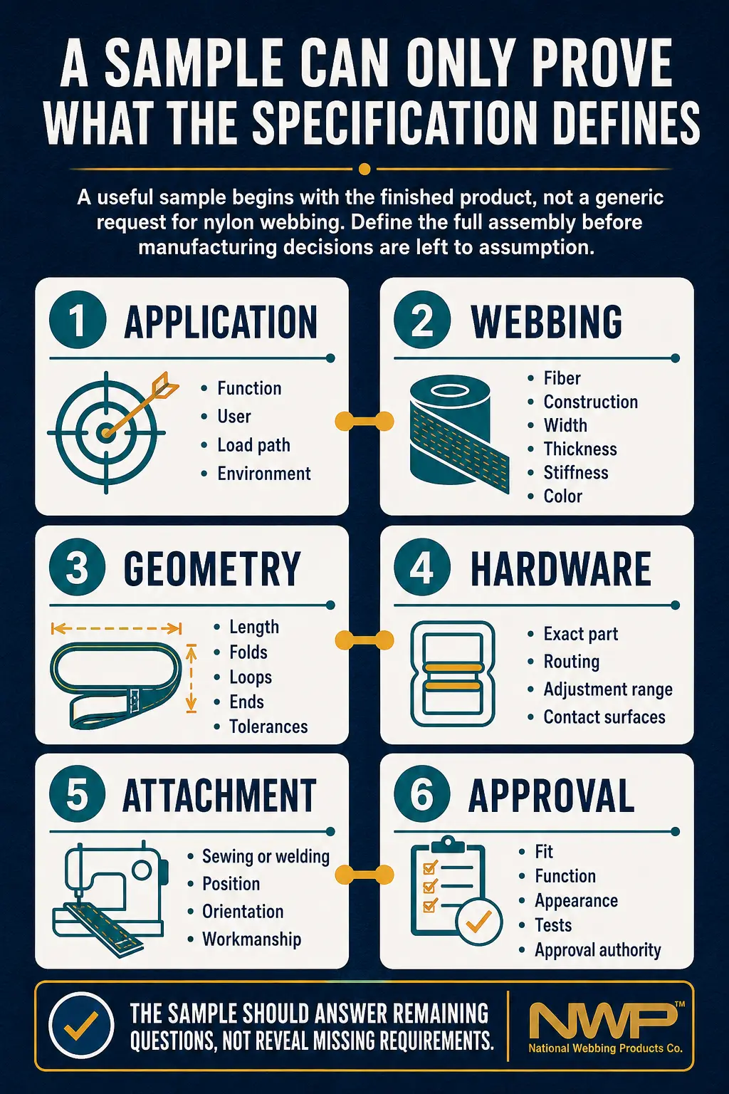
The prevention process starts with a controlled drawing and an exact webbing-and-hardware combination. Develop the attachment around the real load direction, routing, available space, user interaction, and environmental conditions, then review it in the finished geometry. Testing should state the specimen construction, conditioning, method, acceptance criterion, and failure mode rather than reporting only a peak number. If any material, hardware, stitch, or process variable changes, the team should decide whether the original result still applies before releasing production.
At National Webbing, we can help manufacturers develop both the narrow fabric and the completed assembly, so attachment questions can be addressed before components are purchased separately. We still need the customer's application requirements and any governing product standard because the appropriate verification depends on the finished product. A representative mating component or complete routing drawing is particularly useful when clearances and pull direction are difficult to explain. That information lets us focus sampling on the interface most likely to control the design.
An attachment becomes the weak point when it limits function or performance before the rest of the assembly reaches its requirement. Preventing that outcome requires more than selecting a familiar stitch pattern, welding process, or buckle. Treat the webbing, attachment, hardware, routing, workmanship, and loading condition as one defined system. National Webbing can review that system and prepare a representative sample when we receive the actual construction and use requirements. The result should be a validated assembly decision, not an assumption based on one component's strength.
